John Pepper, PE, Principal Engineer, Nextremity Solutions02.12.18
There are many factors that go into making a great orthopedic system. Along the way, one develops a series of engineering guidelines—the result of a substantial number of successful and unsuccessful approaches used in working with a variety of orthopedic technology companies as well as numerous talented surgeons. Unfortunately, one rule rings true above all else—there are no shortcuts to making a great system.
Rule #1: Thou Shall Not Design to Sawbones
The plastic models supplied to a designer by companies are an incredible asset to help develop products. Arguably, without them, the job could not be completed. They serve as effective communication tools, and should be brought to all surgeon and corporate team meetings. They are invaluable for performing practice surgical procedures. Mistakes are caught when putting an implant on a plastic bone model.
The limitations of these devices, however, is that they are a single sample in size and shape. People, on the other hand, do not come with such conformity. The shapes of contoured surfaces can vary greatly. It is better to have access to a database of images, scans, or three-dimensional points. It is also wise to request a sufficient sample size to establish a static significant sample of the key dimensional parameters. Often, this data does not exist and must be created from images.
Body parts vary greatly. For example, first metatarsals have differently shaped facets on the head, and various locations of these facets.1
Also, the plastic models may reflect areas of the body that present as healthy. The remodeling that occurs associated with disease states, such as spinal stenosis and hallux valgus, are often highly irregular. Companies are now offering models of these types of pathologies more often.
Finally, the absence of soft tissues makes it easy to assume that if a procedure can be performed on a model, the design is a success. Unfortunately, that’s hardly an accurate assumption. The overlying structures must be considered, especially when designing an instrument.
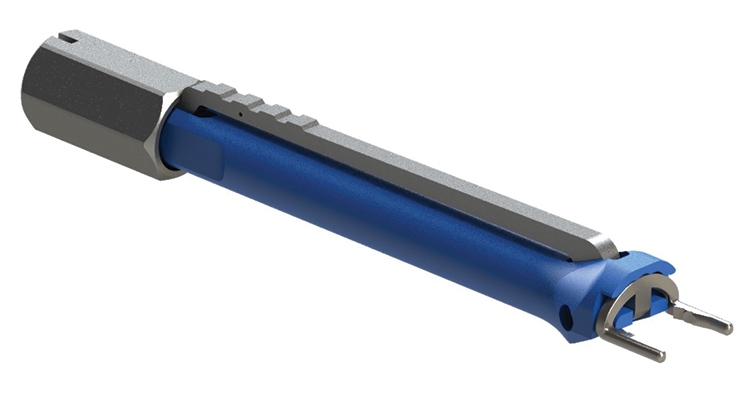
For example, while developing a universal intramedullary nail extractor, the prototype was presented to Toney Russell, M.D., the designing surgeon. The design had been deemed a success based on how it grabbed a nail and pulled it out. The scar tissue that formed over the implant, however, was never considered or addressed within the design of the device.
Dr. Russell suggested a pound of bacon be placed over the implant as a test. The prototype could not advance through the tough material and the design was sent back to the drawing board. Once redesigned and given the “bacon test,” the instrument proved successful for penetrating scar tissue.
Use sawbones as guides, but do your homework to ensure the real-world anatomy that could be encountered is reflected during development and when testing a prototype.
Rule #2: Unless You Have Performed the Surgery 100 Times, Listen to the Surgeon
This rule is partially based upon a humorous question: What is the difference between an orthopedic sales rep and an orthopedic engineer? The rep thinks he or she can do the surgery; an engineer knows he or she can do it. This is a poke at ourselves.
Prior to entering engineering school, I was a hobby cabinet maker. Many people will comment, upon seeing the tools of the trade, that surgery and carpentry are related. Engineers in this field are usually well endowed with hands-on ability. Therefore, it is logical to assume the skills are transferable to a new medium—bone. I had a rude awakening during graduate school, however, while performing veterinary surgery.
A transverse osteotomy appeared to be a relatively simple task. After scrubbing in, opening, being bloody, and having a mobile leg, it proved to be much trickier than anticipated. After several more cases, there was improvement, and after 34 surgeries, the results began to be more consistent. The teachable moment was realized part way through this process: Surgery is much harder than it looks.
Engineers never get to perform the surgeons’ jobs or receive the tactile feedback they do. Operating on the human body is a much different exercise than working with wood. The lack of grip, sliding bones, slick work surfaces, and poor visibility make it vastly different from the experience gained in the garage or machine shop. In order to know what the real and most important issues are, engineers need to listen intently to the surgeon. Assume nothing, and ask all of the questions you may have for the designing surgeon pertaining to the approach, incision size, or any other aspect of a procedure. Assumptions made here regularly sink products, schedules, and budgets.
It is easy to assume that problems in the operating room are caused by a surgeon with bad hands and, while these individuals exist, it is more often due to the unexpected in surgery. Always listen intently to the one who’s actually doing the work.
Rule #3: Surgery Is Hard Enough; The Instruments Should Not Make It Harder
This rule was developed while observing a spine surgeon who specializes in minimally invasive surgical (MIS) approaches. He was working through a 10-centimeter-long tube with a five-degree field of vision next to exiting nerve roots. The dural sac was adjacent to the bone being removed using a high-speed burr. The entire operation was more challenging than many will ever encounter in their life. One single mistake could have ended the surgeon’s career and, potentially, the patient’s life.
Within this type of environment, an awkward or overly complex instrument should never be a part of the system. It must work, preferably with one hand, and be equipped with intuitive controls. It should be obvious how it is to be used. For example, some high-end mechanics’ ratchets offer good controls for direction and release, and could be used as a benchmark. The safety on the AR platform is another example of a simple control motion.
Instructions laser etched onto the tools need to be extremely visible. Ideally, text should be visible from about seven feet away.
Actions need to be smooth and forces of instrument slip or failure need to be designed to go in a direction or magnitude that will be away from and not harmful to adjacent neuro-vascular structures. The Hippocrates oath applies to medical device engineers too, “First, do no harm.”
This rule could be restated as the KISS principle; however, the acronym is derived from Keep Instruments for Surgery Simple.
Rule #4: Saving a Minute in the OR Is Worth the Effort It Takes to Make that Happen
This rule could be titled “Operating Room (OR) Industrial Engineering.” The cost of OR time is quite high. It may even be higher when it means more work for a doctor who could be tired, and a patient who should be under for as short a time as possible.
Often, improvements that can save time become obvious only after testing with a nearly completed system. It is very easy to let momentum on a design stop any further improvements.
A common statement heard by device developers is, “We’ll add that feature in the update next year.” This approach is common in Silicon Valley software startups, as iterations are accomplished by editing lines of code. Medical device implementation cycle times are long and often expensive. Updates are fairly infrequent, if they occur at all. Therefore, the difference between a good and a great system is the willingness of the development team to take advantage of the lessons that typically only materialize late in the evaluation phase.
This is especially true in changes that support Rule #3. Any time savings is especially beneficial. A nice, simple system will sell itself, especially if the time or effort savings is apparent. Engineers can make any implant or instrument work, even if it is very challenging. One to three weeks of delay in development can translate to a product that substantially exceeds mediocre competition.
Rule #5: Use Common Angles for Drilling and Cutting
Humans seem to be conditioned to think in terms of parallel and perpendicular. They are easy to communicate, set up, and make. Ask someone to make a perpendicular cut, and it will happen correctly in most cases. Ask them to make a 70-degree cut, and the result may not be exactly as expected.
If the system requires specialized cuts, provide cutting guides for blades or drill bits. Freehand only when absolutely necessary.
Rule #6: CAD the Entire Assembly with Full Motion
Computer-aided drafting software provides a wonderful surgical device design planning tool. When implementing this tool, include all bones and instruments as accurately as possible. Also, don’t be afraid to use a more simplified, blocky concept to represent an aspect of a system for which a model doesn’t exist yet. Anything is better than omitting a part of the system. Fortunately, libraries such as GrabCAD have increasing numbers of good bone models.
The CAD assembly file can use configurations to show every step of a procedure, starting with the anatomy only. As new parts are added with each step, inferences regarding the instruments will become apparent. Using configurations allows for a straightforward path between surgical steps. Manual suppression leaves too much chance to miss a step.
Though motion of the different elements is often tricky, having everything move in a natural way is even better. This capability can be used as a type of virtual surgery during design meetings to demonstrate to surgeons what is being planned. This can save time by catching obvious oversights, but should never be considered an alternative to a cadaver lab.
Months of practice is required to develop the skills necessary to have CAD software perform as described, but it is well worth the investment.
Rule #7: Test Early and Often
When there is a critical mechanical feature the system depends upon, break it out and perform testing on it. For example, if the locking system is critical, fabricate test parts to decrease the evaluation period. Desktop 3D printers can be especially useful here. If the actual size of the parts is too small with which to work, fabricate them at five times scale. Examining the critical path, either formally or informally, will reveal the required parts to be tested. Too often, systems are considered production ready before being proven out. Ask a novice to check it. See what they balk at or what breaks. The marketing personnel, office staff, or spouses can provide a second opinion on system operation that can be invaluable. Ask others for a third and fourth opinion too.
Physical testing will show any errors in assumptions. It can be the only way to expose some issues. CAD simulations are fantastic time savers, but a design must be proven out with an actual, physical representation of the system. The real-world test is one that must be passed.
Rule #8: Use Round Numbers
Using numbers that are easy to remember makes life simpler in the operating room, machine shop, and conference room. Saying a 6-mm hole, as opposed to a 5.87-mm hole, is preferred. This is true for the machinists and inspectors as well, which could translate to fewer production problems.
Having spacing increments that are simple and intuitive help the system look better in the marketplace. It makes performing the inevitable math faster, which relates back to Rule #3.
Rule #9: Use Stock Components Wherever Possible
Work hard to avoid custom components if a stock part can be utilized. A glance through parts catalogs or supplier websites can yield numerous ideas for helpful time savers. Barrel bolts are a good example. They are used often, not easily remembered, and have numerous names.
Sizing finished instrument shafts to be slightly under bar stock sizes can save on machine time. This seems inconsistent, but if a shaft is just smaller than the bar, a cleanup cut can generate the final dimension, as we can’t use mill finish of the stock bars themselves.
Rule #10: Parts in Tension Have Less Trouble Than in Compression
With the MIS trend and the increasing sophistication of instruments, more compact and higher featured components are being created. When putting the design together, sometimes we can transfer large forces either with a part in compression or in tension. The parts in tension can be smaller as there is no need to add additional material to compensate for possible buckling of parts in compression. Tensioned parts can be smaller, and function better, and therefore are better suited to MIS instrumentation.
Conclusion
Part design and approach varies greatly from engineer to engineer. The guidelines presented in this article are simply one engineer’s principles that have been used to create the best possible surgical systems. The list could be increased; what guidelines would you add for your own set of requirements based on your product development experiences? Hopefully, this list is used as a guide by new engineers and surgeons as they develop their own design principal lists.
Reference
1 Hyer, et al, JFAS, Volume 44, Issue 3, May–June 2005, Pages 200-202.
John Pepper, PE, principal engineer at Nextremity Solutions, is a 28-year industry veteran with 60 issued patents. He has a BSME from Worcester Polytechnic Institute and an MS in biomedical engineering from the University of Texas.
Rule #1: Thou Shall Not Design to Sawbones
The plastic models supplied to a designer by companies are an incredible asset to help develop products. Arguably, without them, the job could not be completed. They serve as effective communication tools, and should be brought to all surgeon and corporate team meetings. They are invaluable for performing practice surgical procedures. Mistakes are caught when putting an implant on a plastic bone model.
The limitations of these devices, however, is that they are a single sample in size and shape. People, on the other hand, do not come with such conformity. The shapes of contoured surfaces can vary greatly. It is better to have access to a database of images, scans, or three-dimensional points. It is also wise to request a sufficient sample size to establish a static significant sample of the key dimensional parameters. Often, this data does not exist and must be created from images.
Body parts vary greatly. For example, first metatarsals have differently shaped facets on the head, and various locations of these facets.1
Also, the plastic models may reflect areas of the body that present as healthy. The remodeling that occurs associated with disease states, such as spinal stenosis and hallux valgus, are often highly irregular. Companies are now offering models of these types of pathologies more often.
Finally, the absence of soft tissues makes it easy to assume that if a procedure can be performed on a model, the design is a success. Unfortunately, that’s hardly an accurate assumption. The overlying structures must be considered, especially when designing an instrument.
For example, while developing a universal intramedullary nail extractor, the prototype was presented to Toney Russell, M.D., the designing surgeon. The design had been deemed a success based on how it grabbed a nail and pulled it out. The scar tissue that formed over the implant, however, was never considered or addressed within the design of the device.
Dr. Russell suggested a pound of bacon be placed over the implant as a test. The prototype could not advance through the tough material and the design was sent back to the drawing board. Once redesigned and given the “bacon test,” the instrument proved successful for penetrating scar tissue.
Use sawbones as guides, but do your homework to ensure the real-world anatomy that could be encountered is reflected during development and when testing a prototype.
Rule #2: Unless You Have Performed the Surgery 100 Times, Listen to the Surgeon
This rule is partially based upon a humorous question: What is the difference between an orthopedic sales rep and an orthopedic engineer? The rep thinks he or she can do the surgery; an engineer knows he or she can do it. This is a poke at ourselves.
Prior to entering engineering school, I was a hobby cabinet maker. Many people will comment, upon seeing the tools of the trade, that surgery and carpentry are related. Engineers in this field are usually well endowed with hands-on ability. Therefore, it is logical to assume the skills are transferable to a new medium—bone. I had a rude awakening during graduate school, however, while performing veterinary surgery.
A transverse osteotomy appeared to be a relatively simple task. After scrubbing in, opening, being bloody, and having a mobile leg, it proved to be much trickier than anticipated. After several more cases, there was improvement, and after 34 surgeries, the results began to be more consistent. The teachable moment was realized part way through this process: Surgery is much harder than it looks.
Engineers never get to perform the surgeons’ jobs or receive the tactile feedback they do. Operating on the human body is a much different exercise than working with wood. The lack of grip, sliding bones, slick work surfaces, and poor visibility make it vastly different from the experience gained in the garage or machine shop. In order to know what the real and most important issues are, engineers need to listen intently to the surgeon. Assume nothing, and ask all of the questions you may have for the designing surgeon pertaining to the approach, incision size, or any other aspect of a procedure. Assumptions made here regularly sink products, schedules, and budgets.
It is easy to assume that problems in the operating room are caused by a surgeon with bad hands and, while these individuals exist, it is more often due to the unexpected in surgery. Always listen intently to the one who’s actually doing the work.
Rule #3: Surgery Is Hard Enough; The Instruments Should Not Make It Harder
This rule was developed while observing a spine surgeon who specializes in minimally invasive surgical (MIS) approaches. He was working through a 10-centimeter-long tube with a five-degree field of vision next to exiting nerve roots. The dural sac was adjacent to the bone being removed using a high-speed burr. The entire operation was more challenging than many will ever encounter in their life. One single mistake could have ended the surgeon’s career and, potentially, the patient’s life.
Within this type of environment, an awkward or overly complex instrument should never be a part of the system. It must work, preferably with one hand, and be equipped with intuitive controls. It should be obvious how it is to be used. For example, some high-end mechanics’ ratchets offer good controls for direction and release, and could be used as a benchmark. The safety on the AR platform is another example of a simple control motion.
Instructions laser etched onto the tools need to be extremely visible. Ideally, text should be visible from about seven feet away.
Actions need to be smooth and forces of instrument slip or failure need to be designed to go in a direction or magnitude that will be away from and not harmful to adjacent neuro-vascular structures. The Hippocrates oath applies to medical device engineers too, “First, do no harm.”
This rule could be restated as the KISS principle; however, the acronym is derived from Keep Instruments for Surgery Simple.
Rule #4: Saving a Minute in the OR Is Worth the Effort It Takes to Make that Happen
This rule could be titled “Operating Room (OR) Industrial Engineering.” The cost of OR time is quite high. It may even be higher when it means more work for a doctor who could be tired, and a patient who should be under for as short a time as possible.
Often, improvements that can save time become obvious only after testing with a nearly completed system. It is very easy to let momentum on a design stop any further improvements.
A common statement heard by device developers is, “We’ll add that feature in the update next year.” This approach is common in Silicon Valley software startups, as iterations are accomplished by editing lines of code. Medical device implementation cycle times are long and often expensive. Updates are fairly infrequent, if they occur at all. Therefore, the difference between a good and a great system is the willingness of the development team to take advantage of the lessons that typically only materialize late in the evaluation phase.
This is especially true in changes that support Rule #3. Any time savings is especially beneficial. A nice, simple system will sell itself, especially if the time or effort savings is apparent. Engineers can make any implant or instrument work, even if it is very challenging. One to three weeks of delay in development can translate to a product that substantially exceeds mediocre competition.
Rule #5: Use Common Angles for Drilling and Cutting
Humans seem to be conditioned to think in terms of parallel and perpendicular. They are easy to communicate, set up, and make. Ask someone to make a perpendicular cut, and it will happen correctly in most cases. Ask them to make a 70-degree cut, and the result may not be exactly as expected.
If the system requires specialized cuts, provide cutting guides for blades or drill bits. Freehand only when absolutely necessary.
Rule #6: CAD the Entire Assembly with Full Motion
Computer-aided drafting software provides a wonderful surgical device design planning tool. When implementing this tool, include all bones and instruments as accurately as possible. Also, don’t be afraid to use a more simplified, blocky concept to represent an aspect of a system for which a model doesn’t exist yet. Anything is better than omitting a part of the system. Fortunately, libraries such as GrabCAD have increasing numbers of good bone models.
The CAD assembly file can use configurations to show every step of a procedure, starting with the anatomy only. As new parts are added with each step, inferences regarding the instruments will become apparent. Using configurations allows for a straightforward path between surgical steps. Manual suppression leaves too much chance to miss a step.
Though motion of the different elements is often tricky, having everything move in a natural way is even better. This capability can be used as a type of virtual surgery during design meetings to demonstrate to surgeons what is being planned. This can save time by catching obvious oversights, but should never be considered an alternative to a cadaver lab.
Months of practice is required to develop the skills necessary to have CAD software perform as described, but it is well worth the investment.
Rule #7: Test Early and Often
When there is a critical mechanical feature the system depends upon, break it out and perform testing on it. For example, if the locking system is critical, fabricate test parts to decrease the evaluation period. Desktop 3D printers can be especially useful here. If the actual size of the parts is too small with which to work, fabricate them at five times scale. Examining the critical path, either formally or informally, will reveal the required parts to be tested. Too often, systems are considered production ready before being proven out. Ask a novice to check it. See what they balk at or what breaks. The marketing personnel, office staff, or spouses can provide a second opinion on system operation that can be invaluable. Ask others for a third and fourth opinion too.
Physical testing will show any errors in assumptions. It can be the only way to expose some issues. CAD simulations are fantastic time savers, but a design must be proven out with an actual, physical representation of the system. The real-world test is one that must be passed.
Rule #8: Use Round Numbers
Using numbers that are easy to remember makes life simpler in the operating room, machine shop, and conference room. Saying a 6-mm hole, as opposed to a 5.87-mm hole, is preferred. This is true for the machinists and inspectors as well, which could translate to fewer production problems.
Having spacing increments that are simple and intuitive help the system look better in the marketplace. It makes performing the inevitable math faster, which relates back to Rule #3.
Rule #9: Use Stock Components Wherever Possible
Work hard to avoid custom components if a stock part can be utilized. A glance through parts catalogs or supplier websites can yield numerous ideas for helpful time savers. Barrel bolts are a good example. They are used often, not easily remembered, and have numerous names.
Sizing finished instrument shafts to be slightly under bar stock sizes can save on machine time. This seems inconsistent, but if a shaft is just smaller than the bar, a cleanup cut can generate the final dimension, as we can’t use mill finish of the stock bars themselves.
Rule #10: Parts in Tension Have Less Trouble Than in Compression
With the MIS trend and the increasing sophistication of instruments, more compact and higher featured components are being created. When putting the design together, sometimes we can transfer large forces either with a part in compression or in tension. The parts in tension can be smaller as there is no need to add additional material to compensate for possible buckling of parts in compression. Tensioned parts can be smaller, and function better, and therefore are better suited to MIS instrumentation.
Conclusion
Part design and approach varies greatly from engineer to engineer. The guidelines presented in this article are simply one engineer’s principles that have been used to create the best possible surgical systems. The list could be increased; what guidelines would you add for your own set of requirements based on your product development experiences? Hopefully, this list is used as a guide by new engineers and surgeons as they develop their own design principal lists.
Reference
1 Hyer, et al, JFAS, Volume 44, Issue 3, May–June 2005, Pages 200-202.
John Pepper, PE, principal engineer at Nextremity Solutions, is a 28-year industry veteran with 60 issued patents. He has a BSME from Worcester Polytechnic Institute and an MS in biomedical engineering from the University of Texas.