Thomas Van Wilpe, Manufacturing Engineer, Lowell Inc05.26.22
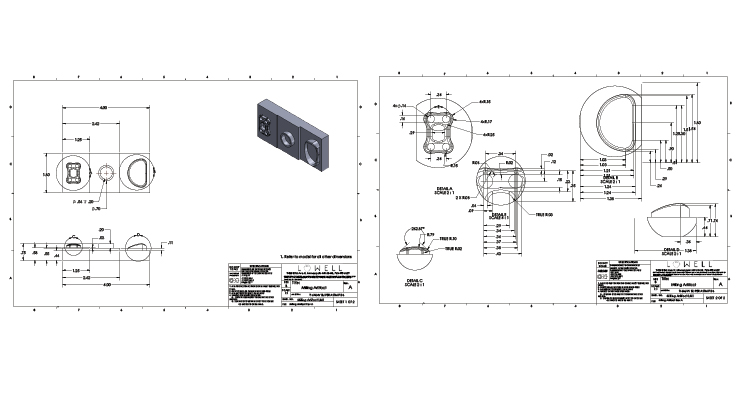
Timelines are a top concern in orthopedic device contract manufacturing for both the company making the product and the OEM seeking to avoid time-to-market delays. In trying to move production along as quickly as possible in the design phase, it’s common to use automated dimensioning functions in 3D CAD software. Adding some data parameters and clicking through the module quickly generates dimensions across a drawing. This generates a drawing that appears ready to hand off to manufacturing.
There are risks, however, to this automated approach; these may only be found once a contract manufacturer reviews the drawing and prepares for manufacturing. Common issues with automated dimensions that may affect timelines include:
Risk #1: Auto dimensioning often adds redundant dimensions, which may lead to longer inspection times. Redundant dimensions are at risk of auto dimensioning if an engineer does not manually remove them before sending the drawing to their manufacturing partner. When contract manufacturers inspect 100 percent of lots to an AQL sample size, every dimension on a drawing has to be inspected and reported on—even the redundant ones.
It’s possible to work with customers to skip redundant dimension inspection through a written agreement. When that’s not possible, redundant dimensions can quickly increase the amount of time engineering and quality assurance need to review. It can be especially costly for the OEM when inspections require expensive inspection equipment or solutions that are time consuming to program.
Manual dimensioning allows an engineer to avoid the risk of redundant dimensions on the drawing or save the extra step of removing redundancies.
Risk #2: Automated dimensions use linear dimensioning, which may make inspections more difficult and costly than if profile tolerancing is used. Auto dimensions rely on linear dimensions and can be set up to automatically add either symmetrical or bilateral dimensions. This dimensioning approach often means the manufacturing team needs to perform extra calculations to complete inspections, which adds complexity and time. Profile tolerancing would be a better option but requires a manual dimensioning approach.
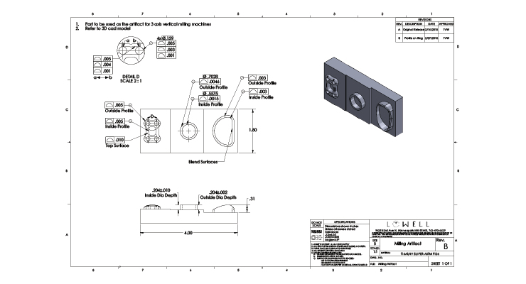
Profile tolerancing is a method that defines uniform upper- and lower-level boundaries around a physical geometry. Rather than having separate dimensions called out for size, form, orientation, or location—which is required with linear dimensioning—profile simplifies this into one description. It can reduce clutter on a drawing and also clarify dimensions for the contract manufacturer.
For example, auto dimensions may call out the location of radii by connecting tangent edges using linear dimensioning. During inspection, the team will have to run calculations to determine the location of the radii. Instead, if the radii were called out from the center point, a quicker measurement could be made with a manual optical comparator or other vision system. Better yet, if the radii were toleranced as a profile, this could be detected by a coordinate measuring machine (CMM) or visual measurement system (VMS) and compared directly to the model.
Another common instance where profile could improve inspection is when the walls of a part are tapered at an angle. With linear dimensioning, linear widths are called out to theoretical sharp corners when a radius is applied to the edge. Without profile tolerancing, the quality team needs to calculate the theoretical sharp corner after creating a measurement program. With profile tolerancing, the team could use a CMM or VMS to compare physical points on the part to the model, saving time and expense on calculations.
Risk #3: Parts are poorly toleranced because tolerances default to the title block. The title block on a drawing shows the default tolerances allowed by a company. If a feature requires different tolerances, the engineer has to add them to the drawing.
With auto dimensioning functions, tolerances are not automatically applied to drawings. If the tolerance isn’t added, the manufacturer will default to the title block. In some cases, this may be fine, but in others, it can lead to tolerance stackup issues if a part or feature’s tolerance need to be different.
Accurate tolerance stackups in medical device assemblies are important to ensure all components fit together and function in real life, not only as designed. If a stackup isn’t correct, the parts may not fit together, and the drawing will need to be revised. This can be costly and time consuming.
Manual dimensioning can remove the risk of missing tolerances on a drawing because all dimensions and tolerances are added separately. This can help alleviate issues with inaccurate tolerance stackups.
Risk #4: You need more meetings and time to clarify design intent that’s lost through auto dimensioning. Auto dimensioning can do many things, but its ability to translate an engineer’s design intent is limited. When design intent is lost, the desired functionality of the part doesn’t come through in the drawing.
The best drawings communicate design intent. Design intent is one of the most important aspects of a medical device’s design, as it gives your contract manufacturer an understanding of how the device will be used and why.
Without this context, it’s more difficult for contract manufacturers to make recommendations to improve the manufacturing process. It also limits their understanding of how a component fits within a larger assembly if they’re only responsible for one component.
One example is dimensions for a slip fit vs. press fit in an assembly. A customer wanted a loose slip fit on a component, but the assembly’s specs and dimensions looked like a press fit was required. The fit of the device component needed to be reworked to match the design intent of the part.
When an issue like this emerges, the contract manufacturer has to follow up with clarification questions, potentially adding time to a project. If auto dimensioning saved a few hours of manual dimensioning time, this savings could easily be lost in additional meetings and communications.
OEMs who take a manual dimensioning approach can find better opportunities to clarify design intent. When only relevant dimensions are added, there’s lower risk of redundancies, it’s easier to take note of which tolerances need to be applied, and inspection can be streamlined. This ultimately improves the manufacturing process and can reduce the impact on timelines.
Thomas Van Wilpe is a manufacturing engineer at Lowell Inc. A graduate of Pittsburg State University with a degree in mechanical engineering technology, he came to Lowell in July 2016. Van Wilpe spent time in inspection and operations before assuming his role as manufacturing engineer, where his focus is on development of manufacturing processes, fixtures, and work instructions.
There are risks, however, to this automated approach; these may only be found once a contract manufacturer reviews the drawing and prepares for manufacturing. Common issues with automated dimensions that may affect timelines include:
- Redundant dimensions, which may lead to longer inspection times
- Outdated linear dimensioning schemes, which can make inspection more difficult or may not truly represent design intent
- Poorly communicated tolerances, which can create inaccurate tolerance stackups
- More meetings to clarify design intent, which may add time to the project
Risk #1: Auto dimensioning often adds redundant dimensions, which may lead to longer inspection times. Redundant dimensions are at risk of auto dimensioning if an engineer does not manually remove them before sending the drawing to their manufacturing partner. When contract manufacturers inspect 100 percent of lots to an AQL sample size, every dimension on a drawing has to be inspected and reported on—even the redundant ones.
It’s possible to work with customers to skip redundant dimension inspection through a written agreement. When that’s not possible, redundant dimensions can quickly increase the amount of time engineering and quality assurance need to review. It can be especially costly for the OEM when inspections require expensive inspection equipment or solutions that are time consuming to program.
Manual dimensioning allows an engineer to avoid the risk of redundant dimensions on the drawing or save the extra step of removing redundancies.
Risk #2: Automated dimensions use linear dimensioning, which may make inspections more difficult and costly than if profile tolerancing is used. Auto dimensions rely on linear dimensions and can be set up to automatically add either symmetrical or bilateral dimensions. This dimensioning approach often means the manufacturing team needs to perform extra calculations to complete inspections, which adds complexity and time. Profile tolerancing would be a better option but requires a manual dimensioning approach.
Profile tolerancing is a method that defines uniform upper- and lower-level boundaries around a physical geometry. Rather than having separate dimensions called out for size, form, orientation, or location—which is required with linear dimensioning—profile simplifies this into one description. It can reduce clutter on a drawing and also clarify dimensions for the contract manufacturer.
For example, auto dimensions may call out the location of radii by connecting tangent edges using linear dimensioning. During inspection, the team will have to run calculations to determine the location of the radii. Instead, if the radii were called out from the center point, a quicker measurement could be made with a manual optical comparator or other vision system. Better yet, if the radii were toleranced as a profile, this could be detected by a coordinate measuring machine (CMM) or visual measurement system (VMS) and compared directly to the model.
Another common instance where profile could improve inspection is when the walls of a part are tapered at an angle. With linear dimensioning, linear widths are called out to theoretical sharp corners when a radius is applied to the edge. Without profile tolerancing, the quality team needs to calculate the theoretical sharp corner after creating a measurement program. With profile tolerancing, the team could use a CMM or VMS to compare physical points on the part to the model, saving time and expense on calculations.
Risk #3: Parts are poorly toleranced because tolerances default to the title block. The title block on a drawing shows the default tolerances allowed by a company. If a feature requires different tolerances, the engineer has to add them to the drawing.
With auto dimensioning functions, tolerances are not automatically applied to drawings. If the tolerance isn’t added, the manufacturer will default to the title block. In some cases, this may be fine, but in others, it can lead to tolerance stackup issues if a part or feature’s tolerance need to be different.
Accurate tolerance stackups in medical device assemblies are important to ensure all components fit together and function in real life, not only as designed. If a stackup isn’t correct, the parts may not fit together, and the drawing will need to be revised. This can be costly and time consuming.
Manual dimensioning can remove the risk of missing tolerances on a drawing because all dimensions and tolerances are added separately. This can help alleviate issues with inaccurate tolerance stackups.
Risk #4: You need more meetings and time to clarify design intent that’s lost through auto dimensioning. Auto dimensioning can do many things, but its ability to translate an engineer’s design intent is limited. When design intent is lost, the desired functionality of the part doesn’t come through in the drawing.
The best drawings communicate design intent. Design intent is one of the most important aspects of a medical device’s design, as it gives your contract manufacturer an understanding of how the device will be used and why.
Without this context, it’s more difficult for contract manufacturers to make recommendations to improve the manufacturing process. It also limits their understanding of how a component fits within a larger assembly if they’re only responsible for one component.
One example is dimensions for a slip fit vs. press fit in an assembly. A customer wanted a loose slip fit on a component, but the assembly’s specs and dimensions looked like a press fit was required. The fit of the device component needed to be reworked to match the design intent of the part.
When an issue like this emerges, the contract manufacturer has to follow up with clarification questions, potentially adding time to a project. If auto dimensioning saved a few hours of manual dimensioning time, this savings could easily be lost in additional meetings and communications.
Conclusion
Auto dimensioning seems like a good method for saving time, but while it can be quicker on the front end, it can lead to more issues when a contract manufacturer creates the device. This can affect and possibly delay the project.OEMs who take a manual dimensioning approach can find better opportunities to clarify design intent. When only relevant dimensions are added, there’s lower risk of redundancies, it’s easier to take note of which tolerances need to be applied, and inspection can be streamlined. This ultimately improves the manufacturing process and can reduce the impact on timelines.
Thomas Van Wilpe is a manufacturing engineer at Lowell Inc. A graduate of Pittsburg State University with a degree in mechanical engineering technology, he came to Lowell in July 2016. Van Wilpe spent time in inspection and operations before assuming his role as manufacturing engineer, where his focus is on development of manufacturing processes, fixtures, and work instructions.
