Finn Buttgereit, Tommy Schafran, Dirk Theodor Schraeder02.24.23
Additive manufacturing processes are attracting increasing attention in application fields of orthopedic technology. However, due to the comparatively low strengths of classic additively manufactured plastics, this application is mostly limited to low-loaded components. For highly loaded structures (e.g. orthoses for the lower extremities), CFRP is currently frequently used.
In this article, an overview of different automated CFRP processing methods and an assessment of their usability for orthopedic technology is given. In particular, continuous fiber-reinforced FDM—a relatively new process for additive manufacturing of CFRP components—is also classified in this overview, and the associated advantages and disadvantages are critically evaluated. Using the prototypical application of the process to manufacture a foot piece for external fixation, the technical possibilities are demonstrated using a practical example.
About Carbon Fiber-Reinforced Plastic
Carbon fiber-reinforced plastic (CFRP), is a composite material that is an ideal lightweight material due to its low density compared to strength and stiffness and thus finds many use cases in orthopedic technology. Furthermore, the application of additive manufacturing processes within medical technology continues to increase and regularly reaches new areas1. Extensive research activities in the field of additive manufacturing (AM) processes are regularly bringing new processes to market readiness and optimizing existing processes.In addition to cost reductions, the goals here are, for example, the improvement of material properties and simpler applicability. To date, however, the use of AF for the manufacture of CFRP components is not widely used2. In the past, the focus has also more often been on combining additively manufactured components with conventional CFRP components3.
In order to be able to drive forward the further development of tools in a goal-oriented manner and to be able to classify the possibilities of AM in CFRP manufacturing, knowledge of the currently available automated CFRP processing methods is necessary.
Overview of Automated CFRP Processing Methods
In recent years, various approaches have been used to further develop automated and in some cases additive manufacturing of CFRP.
Figure 1: Automated CFRP processing methods: a) Tailored Fibre Placement (with permission from TFP-Tech) b) Fiber Patch Placement (with permission from Cevotec), c) Automated Tape Layering (with permission from Premium Aerotec).
In Tailored Fiber Placement (TFP), a carbon cord (the so-called roving) is automatically stitched in any contour onto a base material with the aid of a numerically controlled machine4,5. In this way, the orientation of the fibers, according to the expected stress, can be precisely specified, resulting in higher stiffness. Subsequently, the tissue is attached to a positive model and the matrix is introduced by means of an infusion process. The base material used is not recyclable6. The properties of the material can be predicted relatively precisely and the characteristics of the CFRP component can be documented automatically. Currently available equipment has a maximum size of 2000x2000mm for the base material and is well established in the market. Advantages of the process are the low scrap rate and a lower fiber waste7. The first companies are already offering preforms produced using TFP specifically for orthotic construction.
In Fiber Patch Placement (FPP), two-dimensional CFRP tissue sections (so-called patches) are automatically placed on a positive model by a robot and then hardened using an infusion process8. This procedure thus corresponds to an automation of the manual process in orthosis construction, which also includes an automated documentation of the construct (arrangement of the CFRP fabric sections). However, the stiffnesses that can be achieved are in some cases lower than with the handcrafted CFRP scrim9.
In Automated Tape Layering (ATL), a continuous prepreg (pre-impregnated 2D fiber fabric) is applied to a workpiece using a robot and cured directly using a heat source. Both FPP and ATL are already well established in aerospace applications. Available equipment allows edge lengths of several meters, but usually only relatively planar structures (e.g., aircraft wings) are fabricated8. There are currently no known use cases of the process in orthopedic technology, which can be explained in particular by the high cost of the equipment.
In additive manufacturing (also known as 3D-printing), fiber reinforcement can be combined with all common AM processes. In this context, three common AM processes that enable CFRP processing are presented below. These are shown schematically in Figure 2.
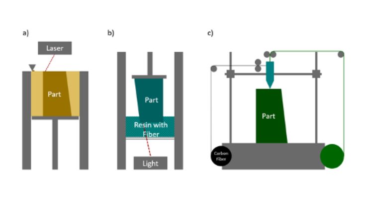
Figure 2: a) SLS with carbon fiber in the powder b) SLA c) Continous fiber reinforced FDM.
Selective laser sintering (SLS), with additive manufacturing of components by sintering a powder by a laser, is a very well-engineered and the fastest growing manufacturing method. Fiber reinforcement has been very little used so far, because according to the current state of development, only chopped fibers (about 20 µm) can be added in the powder, which does not really improve the material properties9.
In sterolithography (SLA), the fiber is added to the resin by mechanical mixing or ultrasonic dispersion, which is then cured under exposure to light10. However, the opacity of the fibers makes it difficult to cure the component uniformly11. Overall, the process is still in the early stages of research and currently there are no known commercially operated devices based on this technology.
Fused Deposition Modeling (FDM), can be combined with short fibers (50-600 µm) or with continuous fibers. The incorporation of the short fibers (typical volume fractions up to 20%) leads to moderate increases in mechanical strengths compared to the base material11, 12. The introduction of continuous fibers can be carried out with the aid of one nozzle, in which the fiber is "impregnated" by the matrix material, or alternatively with two nozzles, so that one nozzle extrudes the fiber and one nozzle extrudes the matrix material13. Since the achievable fiber volume fractions and fiber lengths are significantly higher, the maximum stiffness increases by up to a factor of 18 (at up to 1.5% elongation at break) and tensile strength by as much as a factor of six (this corresponds to up to 80MPa) compared to the base material10,11,14. The installation space of the process is currently limited by the available equipment to 535 x 400 x 400mm14. Currently, only two widespread suppliers for printers with continuous fiber reinforcement are known.
Applicability of Continuous-Fiber-Reinforced FDM for Orthopedic Devices
For an application in the manufacture of patient-specific aids, the FDM process in combination with continuous fiber reinforcement offers advantages over the manual handling of CFRP for the fabrication of orthopedic aids, since the production runs automatically, complex geometries can be manufactured without a positive, and the manufacturing documentation for compliance with existing regulations (like the medical device regulation MDR in the EU) is easier to comply with15. Compared to conventional FDM processes, the higher strength and stiffness offer key advantages.Basically, the process requires a virtual 3D model of the component. This can be generated either by means of a 3D scan or with the aid of parametric computer models. For additive manufacturing, the orientation of the fibers must be determined. This requires more time than slicing for additive manufacturing without continuous fiber reinforcement.
In slicing, the digital model to be manufactured is divided into finitely many two-dimensional slices and further manufacturing parameters are defined. It should also be noted that due to the orientation of the fiber parallel to the direction of construction, the component is significantly weaker mechanically in the built-up direction. This makes it difficult to find an ideal build direction. Complex geometries can be produced, but the introduction of the fiber leads to a restriction of the design freedom compared to conventional FDM, since, for example, wall thicknesses have to be made larger.
The removal of possible support structures, which is often necessary in particular for FDM processes, involves an additional work step, which must be accompanied by post-treatment of the surface to enable disinfectability and, if necessary, sterilizability16. Compared to the manual processing of CFRP, the installation space is currently still a limiting factor, especially with regard to foot orthoses, for instance.
The advantages and disadvantages of using the process are summarized in Table 1:
Table 1: Advantages and disadvantages of continous-fibre-reinforced FDM
| Advantages | Disadvantages |
| Automated manufacturing | Support structures are to be removed |
| Complex geometries | Restricted design freedom |
| No tool/positive model necessary | Anisotropy |
| Manufacturing documentation for compliance with the regulations easier to comply with | Surface quality reduced |
| Higher strength parts possible | Limited build space |
The fact that the application of additive manufacturing processes for the production of highly stressed patient-specific aids can be advantageous in many ways has already been shown for some powder-based additive manufacturing processes using the example of a lower leg orthosis for patients with a Charcot foot17. Due to the good mechanical properties of continuous fiber-reinforced FDM, it can represent a manufacturing alternative for established aids. The design freedom in the process also offers the opportunity to test fundamentally new assistive device designs.
In order to test the possibilities of the process, a device was designed for fabrication using the FDM process with continuous fiber reinforcement. It is a so-called foot piece for an external fixator of the lower extremities, which allows the user early postoperative mobilization. Since the external fixator braces both the lower and upper ankle joints, the footpiece must allow suspension and rolling similar to a foot prosthesis. However, currently established foot pieces usually do not allow a biomechanically correct gait pattern. It is also important that the foot piece is highly efficient, i.e. that it releases the energy input when it rebounds. In prosthesis construction, CFRP springs in various arrangements are classically used for this purpose. These approaches were prototypically combined in a new aid that can be connected to established fixator systems and enables a spring deflection.
The design for the foot piece is based on the spring arrangement of the so-called Lambda foot19. Prior to the design of the device, C-shape test samples were manufactured in order to investigate the spring stiffness, load capacity and fatigue life of the printed material. For this purpose, the dorsal arch of the aid, which dampens the occurrence of the heel, and the attachment points of the distal fixator screws were fabricated separately in three different designs each. All test specimens were fabricated on the Mark Two (Markforged Company) and the Anisoprint Composer A3 (Anisoprint Company). However, due to technical challenges in the printing process (large number of empty spaces), only the manufactured test samples from the Mark Two were able to be used. The test specimens were designed as a matrix of microcarbon fiber filled nylon (brand name Onyx) with continuous carbon fiber with a filling level of 100% infill. The selected fiber arrangement for the test specimens and the test setup is shown in Figure 3. The fabricated specimens were then tested on a testing machine (Instron E-10000) with a loading frequency of 4Hz.
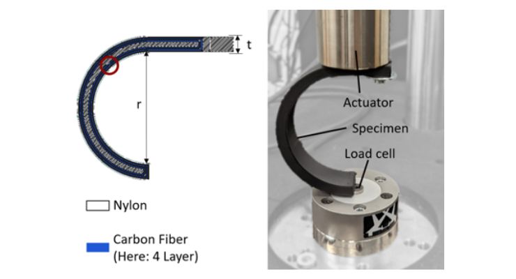
Figure 3: Arrangement of the fiber in the test specimen and Test-Setup. Weak point of the fiber orientation marked in red.
The results from the preliminary tests are listed in Table 2. The efficiency refers to the proportion of the energy that is released again by the component when it deflects.
Table 2: Results of preliminary tests
| Specimen Nr. | Specimen Diameter r [mm] | Thickness t [mm] | Carbon-fibre-Layers | Ultimate Load [N] | Cycles | Load at Cycle | Spring stiffness [N/mm] | Efficiency |
| 1 | 40 | 4 | 2 | 700 | 200.000 | 400 | 130-160 | 95% |
| 150.000 | 500 | 160 | ||||||
| 1000 | 700 | 152 | ||||||
| 2 | 40 | 5 | 2 | 1460 | LTF | - | 141-233 | - |
| 3 | 40 | 6 | 4 | 1900 | 2700 | 1900 | 545,45 | 96,2% |
| 4 | 100 | 5 | 2 | 511 | LTF | - | 26,5-29,4 | - |
| 5 | 100 | 7 | 4 | 1600 | 200.000 | 1000 | 121,9 | 93,4% |
| 3000 | 1200 | 121,9 | ||||||
| 147 | 1600 | 108,1 | ||||||
| 6 | 100 | 9 | 6 | 1500 | 160.000 | 1500 | 216,7 | 97% |
Due to possible variations in the properties in the manufacturing process, the characteristic values determined can only be taken as approximate values20. Based on the described preliminary tests, the foot piece was dimensioned so that it is suitable for a person with a body weight of 80 kg in terms of deflection and load-bearing capacity.
Additive manufacturing was also performed on the Mark Two, with the foot piece lying on the medial side. The completed foot piece is shown with an inserted foot skeleton dummy in Figure 4. Apart from a removal of the support structure, no post-processing was done. The surface shows some minor blobs and pimples, as well as some lines on the surface along the direction of build-up. Underneath the support structure, the surface is very rough (see Figure 4).
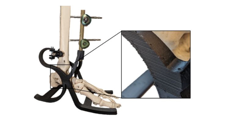
Figure 4: Printed foot piece with connection to the external fixation. The surface has ripples and pimples.
For the above reasons, practical use requires surface finishing. Since no sink marks were visible as surface defects, subtractive post-processing methods (such as tumbling) are applicable. To test the properties, an artificial tibia (3B Scientific) was embedded in a holder at the proximal end and screwed to the base at the distal end using fixator clamps and fixator screws. The holder was inserted into a compression testing device with an adjustable test fixture (self-built by the University of Paderborn). With the aid of the test fixture, the foot piece was loaded plantar between -20° inclination (roughly corresponding to the stress during the heel strike) and +20° inclination (roughly corresponding to the stress during the push-off phase) to the ground in order to simulate the stress of the individual gait phases (see Figure 5). After a complete roll-off cycle, the load was increased by 100N each time to determine the load limits. To prevent slippage, an anti-slip mat was placed on the bottom of the foot piece.
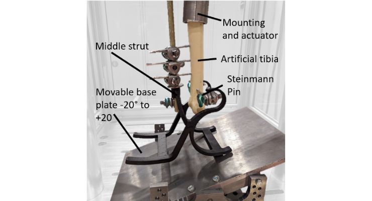
Figure 5: Practical testing at -20° (initial heel strike).
The loads on the front end of the foot piece (+20°inclination) showed that the middle strut had low stiffness and therefore a greater load flow ran through the Steinmann nail (indicated in Figure 5). This was also evident in a displacement of the clamps on the Steinmann nail, which lead to a brief drop in spring stiffness at loads above 200N. Combined with the non-ideally chosen screw arrangement, the degraded stiffness of the center strut led to fracture of the artificial tibia at 653N load on the forefoot. The printed CFRP component did not exhibit any damage. The spring stiffnesses over the tests are shown in Table 3.
Table 3: Spring Stiffness of the tested device
| Force [N] | Spring stiffness -20° (Heel-Strike) [N/mm] | Spring stiffness +20° (push off) [N/mm] |
| 100 | 32,4 | 41 |
| 200 | 25,5 | 29,4 |
| 300 | 31,6 | 30,0 |
| 400 | 31,3 | 36,3 |
| 500 | 30,2 | 38,7 |
| 600 | 27,5 | 30,0 |
| 653 | - | 32,6 (break) |
Conclusion
The additively manufactured CFRP components exhibit high strength and stiffness, which is why the manufacturing process of continuous fiber-reinforced FDM can reveal new possibilities for orthopedic technology. In particular, due to the design freedom, new concepts can be tested relatively quickly in a reproducible manner. Structures along the build-up direction (such as the center strut) have less stiffness because the fibers are arranged next to each other here. Dividing the component into several individual parts that are later joined together can provide a solution, since in this way the fiber alignment can be in different planes within the overall structure.Post-processing of the surfaces is currently required for possible practical use on patients. Similarly, for patient-specific production of assistive devices, it must be clarified with what process reliability the desired geometries can be produced by the currently available printers.
In addition to the possibilities offered by the endless fiber-reinforced FDM process, it remains to be seen whether other automated processes for CFRP production will continue to develop in order to be considered for use in orthopedic technology.
The foot piece developed for the fixator will be adapted based on the tests conducted to ensure an improved loading situation in the future.
Authors:
Finn Buttgereit, University of Paderborn (Applied Mechanics, FAM)
Dr. Ing. Tommy Schafran, Thyssen-Krupp
Dr. Dirk Theodor Schräder, Hospital zum Hl. Geist Geseke
References:
1 Kumar, P.; Rajak, D.; Abubakar, M.; et Al.: 3D Printing Technology for Biomedical Practice: A Review. In: Journal of Materials Engineering and Performance. Vol. 30. S. 5342-5355. 2021
2 Told, R.; Marada, G.; Rendeki, S.: Manufacturing a First Upper Molar Dental Forceps Using Continuous Fiber Reinforced (CFR) Additive Manufacturing Technology with Carbon-Reinforced Polyamide. In: Polymers. Vol. 13. 2021
3 Wojciechowski, E.; Chang, A.; Balassone, D.: Feasibility of designing, manufacturing and delivering 3D printed ankle-foot orthoses: a systematic review. In: Journal of Foot and Ankle Research. 2019
4 Khaliulin, V. I.; Khilov, P. A.; Toroptsova, D. M.; Prospects of applying the tailored fiberplacement (TFP) technology for manufacture of composite aircraft parts, in: Russian Aeronautics (Iz VUZ), 58, 2015.
5 Feltin, D.; Gliesche, K.; Preforms for composite parts made by tailored fibre placement,in: Proceedings of ICCM, 1997.
6 Kim, B.; Hazra, K.; Weaver, P.; Potter, K.; Limitations of fibre placement techniques for variable angle tow composites and their process-induced defects, 2011.
7 Spickenheuer, A.; Fittkau, N.; Konze, S.; et Al.: Anwendung des Tailored-Fiber-Placement-Verfahrens in der Orthopädietechnik. In: Orthopädie-Technik. Vol. 04. 2022
8 Cevotec GmbH; Technologie & Prozess - Cevotec GmbH, 03.08.2020, https://www.cevotec.com/fpp-technologie/. Last Called at 13.01.2022.
9 Baumer, A.; Baeten, A.: Contribution to Structural Mechanics of Patch-Based Composites. In: Proceedings of the 4th International Conference Hybrid 2020:Materials and Strucutres. 2020
10 van de Werken, N.; Tekinalp, H.; Khanbolouki, P.; Ozcan, S.; Williams, A.; Tehrani, M.; Additively manufactured carbon fiber-reinforced composites: State of the art and perspective, in: Additive Manufacturing. Vol. 31, 2020.
11 Parandoush, P.; Lin, D.; A review on additive manufacturing of polymer-fiber composites, in: Composite Structures. Vol. 182, 2017.
12 Tamez, M.; Taha, I.; A review of additive manufacturing technologies and markets for thermosetting resins and their potential for carbon fiber integration, in: Additive manufacturing. Vol. 37, 2021.
13 Penumakala, P.; Santo, J.; Thomas, A.; A critical review on the fused deposition modeling of thermoplastic polymer composites, in: Composites Part B: Engineering, Vol. 201, 2020.
14 Markforged: Materialbeschreibungen – Verbundmaterialien. Verfügbar unter: https://www.mark3d.com/de/wp-content/uploads/2021/04/Material_Datenblatt_Composites_Deutsch.pdf, zuletzt Abgerufen: 20.01.2023.
15 Fittkau, N.; Spickenheuer, A.: Anwendungen des Tailored Fibre Placment Verfahrens für die Orthopädietechnik. Composites United. Verfügbar unter: https://www.youtube.com/watch?v=6eipbVYsEck zuletzt abgerufen 20.01.2023
16 Miron, V.: Additive Manufacturing for Medical Application. Doctoral Thesis. Johannes Kepler Universität Linz. 2021
17 Schafran, T.: Ein Beitrag zur Entwicklung einer additiv gefertigten Unterschenkelorthese unter Berücksichtigung der biomechanischen Aspekte des Charcot-Fußes. Dissertation. Shaker 2020
18 Novastep Inc.: Fusion Frame. Operative Technique. Englewood Cliffs. 2020
19 Medicalexpo: Freedom Innovations. Unter: https://www.medicalexpo.es/prod/freedom-innovations/product-74876-457098.html 15.12.2022. 9:36
20 Toh, S.; Goh, C.; Tan, P.; et Al.: Fatigue testing of energy storing prosthetic feet. In: Prosthetics and Orthotics International. Vol. 17. S.180-188. 1993
21 Morgan, R.; McReynolds, B.; Husmann, K.; et Al.: Markforged Continuous Fiber Composite Material Testing. Technical Report. National Nuclear Security Administration (NNSA). 2020
